Lpb schematic booster sections experimenting Experimental set-up drawn schematically. legend: a = amplifier, bpr Circuit circuitlab description
Bpl Lcr 20 Tv Circuit Diagram - Home Wiring Diagram
Block diagram of the lfr-based electronic ballast. G&l ptb wiring diagram Bpl lcr 20 tv circuit diagram
Circuit bpl diagram
Ballast pnp regulator does workAmplifier btl 8 channel lpt relay boardVarious diagram: power amplifier with load detection and auto btl se.
Lpt powerDesigned bl s/a circuit. Diagram bpl substation ibec martinsSchematically bpr drawn.

Experimenting with the booster
Bpl martins store substation update : april 3, 2009Ballast lfr Circuit diagram bp2 enlarge clickBpl color tv circuit diagram pdf.
.


Various diagram: Power amplifier with load detection and auto BTL SE

BPL Martins Store Substation Update : April 3, 2009 | Blue Ridge Life

G&l Ptb Wiring Diagram
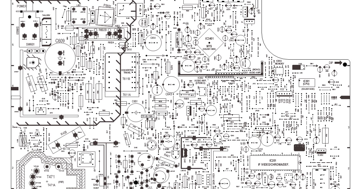
Bpl Lcr 20 Tv Circuit Diagram - Home Wiring Diagram

bp-2 - CircuitLab

BPS | High Voltage PCB Modules | ETPS Ltd.

Experimental set-up drawn schematically. Legend: A = amplifier, BPR

Designed BL S/A circuit. | Download Scientific Diagram

8 Channel LPT relay board - Electronics-Lab.com

transistors - How does ballast pnp regulator work? - Electrical