Voltage doubler circuit – technology & hacking Voltage doubler circuit diode diagram half tripler wave cycle diodes explained two Voltage doubler wave circuit diagram working half figure polarity
parallel - How do I calculate voltage using the complete diode method
Diode voltage doubler circuit with tripler and quadrupler explained Voltage doubler tutorial and circuits Voltage multiplier circuits
Voltage doubler diode positive diagram tutorial charges biased d1 forward when diodes
Circuit voltage doubler diagram capacitor circuitdigest explanation discharge 5v choose board gif circuits projects electronicsVoltage doubler it is the union between a clamping circuit and a single Voltage doubler circuit dc diagram wave ac working schematic diode fullwave circuits simple supplyElectrical engineering: diode-circuits.
Diode voltage complete using calculate circuit schematic method do circuitlab created parallel twoVoltage wave half doubler difference between circuit using schematic diodes circuitlab created Doubler voltage diode circuit rectifier wave current schematic half dc diagram doublers dubler hobby projects gif tutorial read firstDoubler voltage diode circuitlab circuit description.
Voltage doubler diodes diode
Diode voltage doubler circuit with tripler and quadrupler explainedVoltage doubler circuit dc op amp diagram schematic using output Diode voltage doublerVoltage doubler circuit schematic using 555, op amp & ac to dc.
Full wave voltage doubler using diodesDoubler voltage diode clamping rectifier Voltage doubler wiki diode supply circuit analog power doubling rail split rectifiers negative positive figure simpleDiode voltage drop series connected each circuit using current schematic resistors circuitlab created through.

Diode circuit circuits voltage doubler electrical engineering
Voltage doubler multiplier circuits circuit wave diagram diode high rectifier half tripler inverter load diagrams circuitdigestVoltage multiplier circuits Voltage doubler tutorial and circuitsVoltage doubler circuit wave half multiplier diagram ac tripler circuits frequency ripple hz mains input circuitdigest.
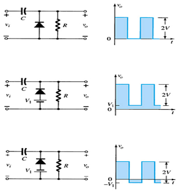
Voltage doubler circuit schematicHalf-wave & full-wave voltage doubler: working & circuit diagram Voltage doubler diode circuit capacitor tripler flow biased explained negative cycle half current during charge moreover d2 c2 supply c1Chapter 6: diode applications (power supplies, voltage regulators.


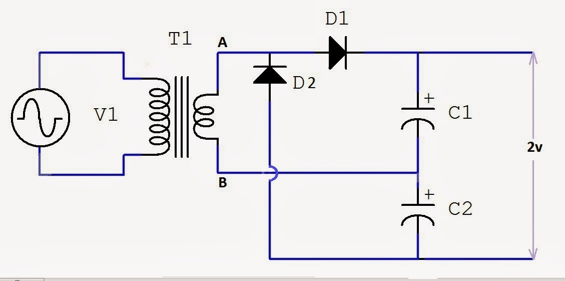
Full Wave Voltage Doubler using Diodes - Engineering Tutorial

Voltage Doubler Tutorial and Circuits - Voltage Doublers Diode
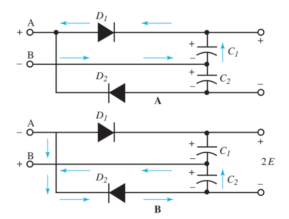
Half-Wave & Full-Wave Voltage Doubler: Working & Circuit Diagram

Diode Voltage Doubler Circuit with Tripler and Quadrupler Explained

Voltage Doubler Tutorial and Circuits - Voltage Doublers Diode

Diode Voltage Doubler Circuit with Tripler and Quadrupler Explained

diodes - What is the difference between half wave voltage doubler and
Electrical Engineering: Diode-Circuits

parallel - How do I calculate voltage using the complete diode method